Annual degree of utilisation

|
ƞa = annual degree of utilisation [%] |
The heat energy Qi,a supplied during a year is determined based on the actual fuel energy used. To do this, the fuel quantity is measured with gas or oil counters and multiplied by the net calorific value.
_einer_Dampfkesselanlage_EN.png)
Sankey diagram (energy flow diagram) of a steam boiler system
|
|
Latent heat of the flue gas |
|
|
Sensible heat of the flue gas |
|
|
Radiation and conduction (including downtime losses) |
|
|
Pre-ventilation losses |
|
|
Surface and bottom blowdown, exhaust vapours |
|
|
Leaks (at the condensate drains, pipework) |
|
|
Missing condensate recirculation and exhaust vapours |
|
|
Recirculated condensate |
The amount of energy actually used during operation Qo,a is determined using a steam meter and a heat quantity calculator. The quantity of heat in the steam is calculated from the quantity of steam and steam pressure, and possibly the temperature of the steam.
When measured and added up over a year and divided by the amount of energy in the fuel, the annual degree of utilisation of the system is obtained.
The annual degree of utilisation of a steam boiler system therefore includes all operational losses of a steam boiler system, such as the flue gas, system, distribution and condensate losses.
A boiler efficiency of 95% may be accompanied by an actual annual degree of utilisation of only 60%. Especially if the average boiler load is very small, the conduction and radiation losses, which generally do not depend on the boiler load, are very high in relation to the fuel heat used. The losses for pre-ventilation of the boiler system during cycling of the burner and for water treatment are added to this.
If the system is frequently only operated in partial load, the losses can occasionally be 20 – 40% of the fuel required for operation of the system.


|
Boiler efficiency with condensing use
In addition to CO2, the flue gas produced during combustion of the hydrocarbon chains found in most liquid or gaseous fuels also includes H2O, i.e. water. At high flue gas temperatures, this water is present in the form of vapour.
However, if the flue gas temperature can be cooled locally to below the dew point, some of the water vapour in the flue gas condenses on the cold heat transfer surfaces and the heat released during this process can be used.
Compared to the formula for a boiler without condensing use, the formula for the boiler efficiency is extended to include the condensation fraction:
The condensate number specifies the ratio between the quantity of condensate which occurs in practice and the quantity of condensate which is theoretically possible in the flue gas and normally has a value of 0.3 – 0.6, depending on the design.
Efficiencies higher than 100% when using condensing technology are not perpetuum mobile, and can instead be traced back purely to the reference basis of the net calorific value Hi. If the energy used were referenced to the physically correct gross calorific value Hs, 100% would be the maximum efficiency that could be achieved without any losses whatsoever. However, to allow comparisons to be drawn with conventional systems, it has been decided to retain the net calorific value as reference value, also in the case of condensing boilers.
Fig. "Heat balance of a steam generator featuring condensing technology and gas combustion"
The difference between the net calorific value and gross calorific value is the latent heat in the flue gas and represents the maximum proportion of heat which can also be recovered due to condensation of the water fraction in the flue gas.
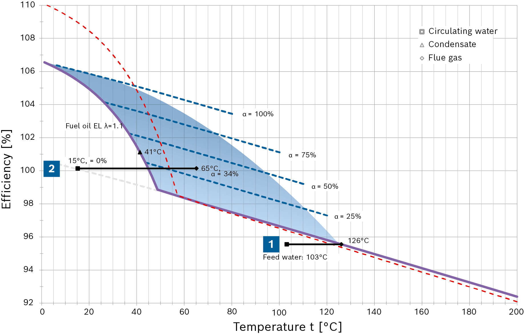
The purpose of the following diagram is to make clear how flue gas condensation increases efficiency and the optimisation in terms of cost-effectiveness.
When using gas as fuel, the efficiency increases in a linear fashion as the flue gas temperature falls until flue gas condensation starts (with a heating surface temperature of roughly 56°C). When condensation in the flue gas starts, the crucial factor is no longer the reduction in temperature, but instead first and foremost the condensation rate α of the water vapour in the flue gas. The diagram shows the different condensation rates of 25, 50, 75 and 100% as dashed blue lines. With a corresponding higher condensation rate, the efficiency continues to increase in jumps.
During this process, the special design of the condensing heat exchanger allows significant quantities of the water in the flue gas to condense at very low water inlet temperatures (e.g. make-up water at 15°C) even when the flue gas temperature measured in the chimney is significantly higher than the flue gas dew point.
In the diagram for natural gas H an efficiency of 100.9% is achieved with a condensate accumulation rate of 34% and a measured average flue gas temperature of 75°C, for example.
Fig. "Combustion efficiency progression as a function of flue gas temperature with natural gas H"
In addition to the quantity of water, the greatest possible distance between the water inlet temperature and minimum dew point is decisive for the condensate accumulation rate. That is shown in the diagram by the red (natural gas H) or purple (fuel oil EL) efficiency curve, which is temperature-dependent.
The area coloured blue represents the technically-achievable flue gas condensation range for steam boiler systems.
|
|
|
|
Natural gas H:
|
Natural gas H:
|
|
Fuel oil EL:
|
Fuel oil EL:
|


Combustion efficiency progression as a function of flue gas temperature with fuel oil EL (Hi = 11.89kWh/kg, TL = 20°C)
Especially when using oil as fuel, it must be observed that because the fuel composition is different to gas, the water vapour fraction in the flue gas is significantly lower and therefore the efficiency gain due to condensation is also correspondingly less.


